Earthquake Analysis with RSA
Introduction
The following tutorial is focused on the workflow for the earthquake analysis based on the Response Spectrum Analysis (RSA) method, including the subsequent design of beam and area elements for the seismic design situation.
Project Description
Please see the following project information before starting to set up your project files.
Materials
Number |
Material |
Strength |
|---|---|---|
1 |
concrete |
C 20/25 |
2 |
reinforcement steel |
S 500 |
Cross Sections
Element |
Dimension |
Weight |
|---|---|---|
Column |
B/H = 30/30 cm |
g = 0,225 t/m |
T-Beam |
B/H/Bw/Hf = 70/60/30/20 cm |
g = 0,300 t/m (w/o slab flange) |
T-Beam, edge |
B/H/Bw/Hf = 50/60/30/20 cm |
g = 0,300 t/m (w/o slab flange) |
Slab |
D = 20 cm |
g = 0,500 t/m² |
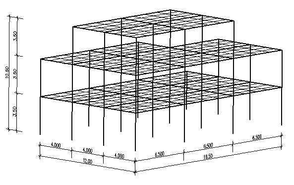
Geometry
Loads
LC Number |
Title |
Loads |
|---|---|---|
1 |
Additional dead load |
g1 = 1,50 kN/m² (100% mass active) |
2 |
Live load |
q2 = 2,00 kN/m² (15% mass active) |
3 |
Roof load |
q3 = 3,00 kN/m² (30% mass active) |
4 |
Wind X (in X direction) |
Load value varies dependent on the position / height of the structure |
5 |
Wind Y (in Y direction) |
Load value varies dependent on the position / height of the structure |
10 |
Self-weight |
automatic generation “Factor of dead weight” = 1.0 |
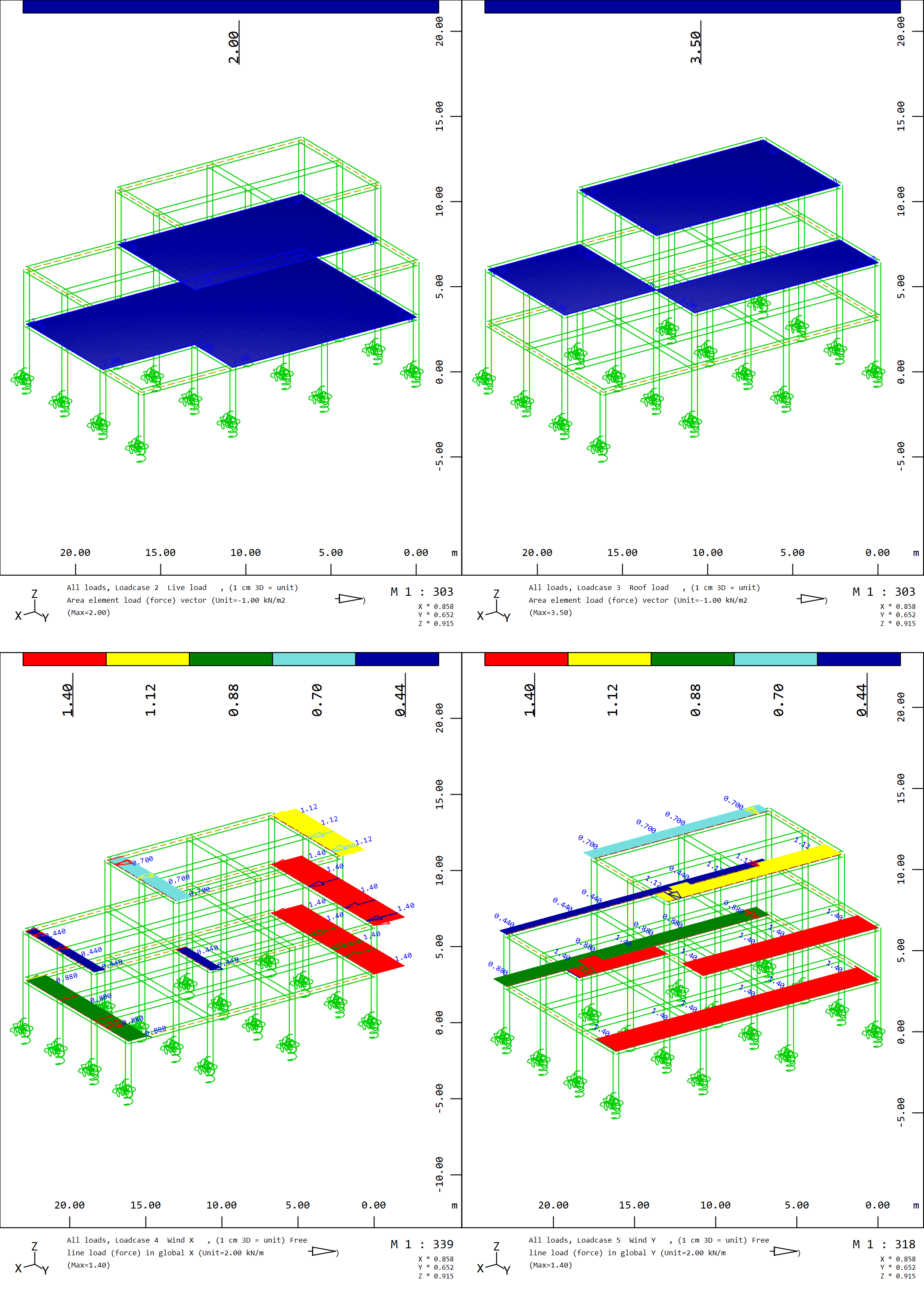
The following picture shows the live load (LC 2), roof load (LC 3), wind in X (LC 4) and Y (LC 5) direction, respectively.
For the Response Spectrum Analysis the following values we will be used
Response Spectrum according Eurocode |
Type 1 –> EC-1 |
Type of Spectrum |
Design Spectrum |
Acceleration |
Ag = 0.8 m/s² |
Soil Class |
A |
SSD Earthquake Task
Title: Earthquake analysis with RSA - SSD Earthquake Task| Quality: 1080p HD | Captions: English
Seismic Design Situation
Combinations of the effects of the actions
After calculating the SSD Earthquake Task, by clicking on the “Define Combinations” Task in the SSD project, the necessary Combination Rules, including the ULS seismic combination Rule, will be generated automatically according to the selected design code. By clicking OK the generated Combination Rules will be saved in the database.
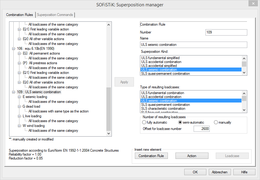
Selection of available results for each of the previously generated Combination rules is availble in the SSD Task “Superpositioning”. In the tutorial only the results of the ULS fundamental and ULS seismic combination are selected. For example, the resulting forces in beam elements for the ULS seismic combination will be stored in loadcases starting with the First Loadcase No. 2621. By clicking OK the selected superpositioning results will be calculated.
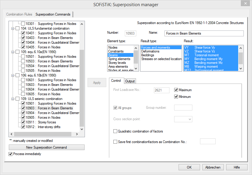
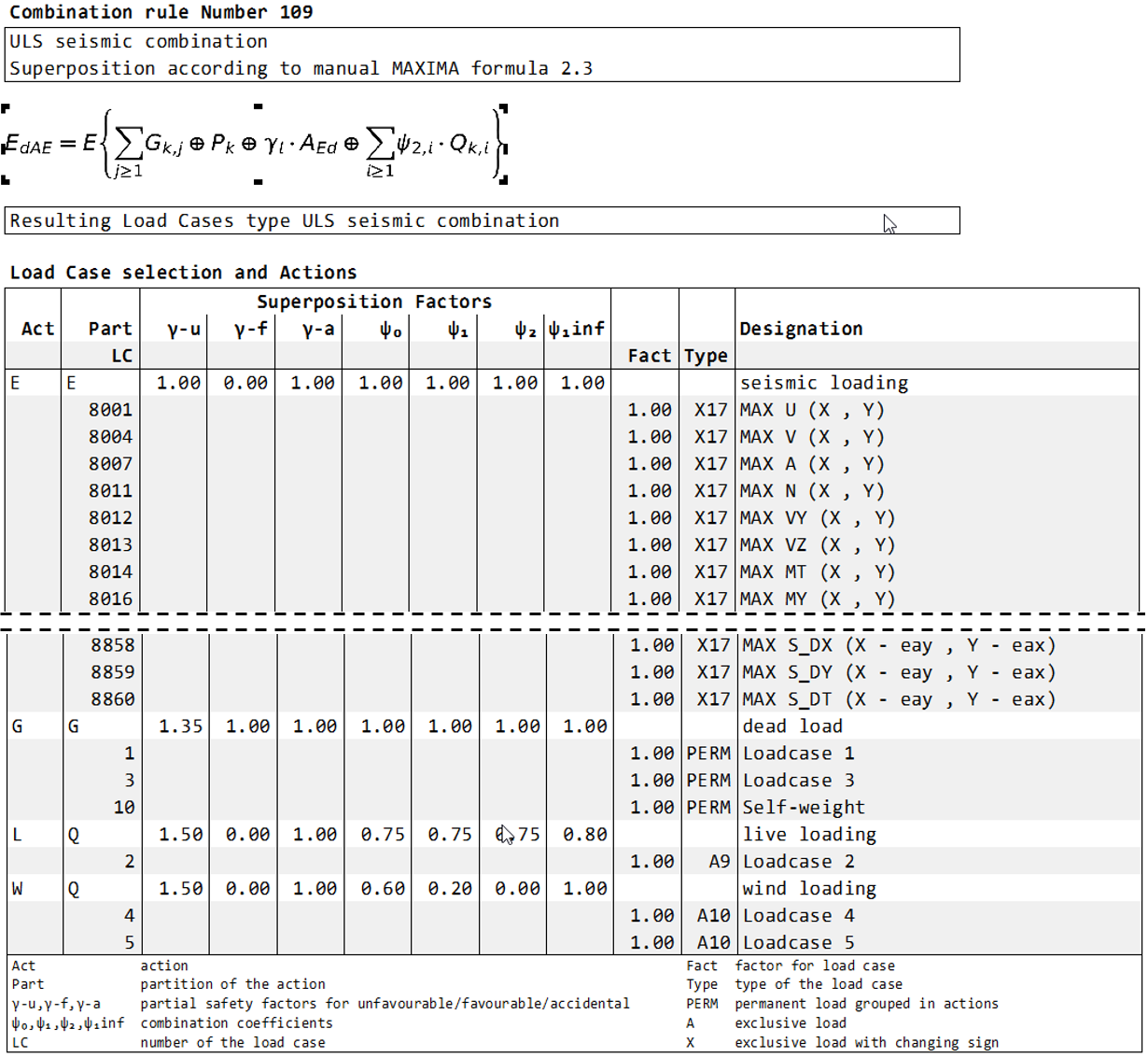
In the generated Superpositioning Report the ULS seismic combination rule 109 and the selection of the associated loadcases for the superposition will be listed.
Determining the required reinforcement
To proceed with the design process, please add the following tasks by using the command “Insert Task” from the context menu, with the right mouse click.
Design ULS (Area elements)
Design SEIS (Area elements)
Design ULS (Beams)
Design SEIS (Beams)
The tasks are sorted in two groups, “Design Area Elements” and “Design Beam Elements”. Furthermore, the task “Design Parameters of area elements” has been added to the “Design Area Elements” group.
The following tutorial is focused on the Seismic Design Situation, i.e. on the tasks “Design SEIS (Area elements)” and “Design SEIS (Beams)”. For more information about the Design at the Ultimate Limit State please see the SSD Video Tutorial, Chapter 6: Design of Area and Beam Elements.
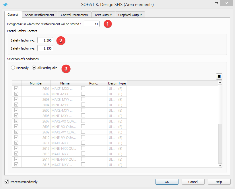
In the task “Design SEIS (Area elements)” the Designcase number for storing the calculated reinforcement needs to be specified, see point (1) in the picture below. By default it is set to 11. According to Eurocde 1998-1, chapter 5.2.4 (2), the safety partial factors for concrete and steel, adopted for the persistent and transient design situations, should be applied. Therefore, they are set as default values in the Task, see point (2). Furthermore, all resulting forces in area elements for the ULS seismic combination will be automatically selected by the Task, see point (3).
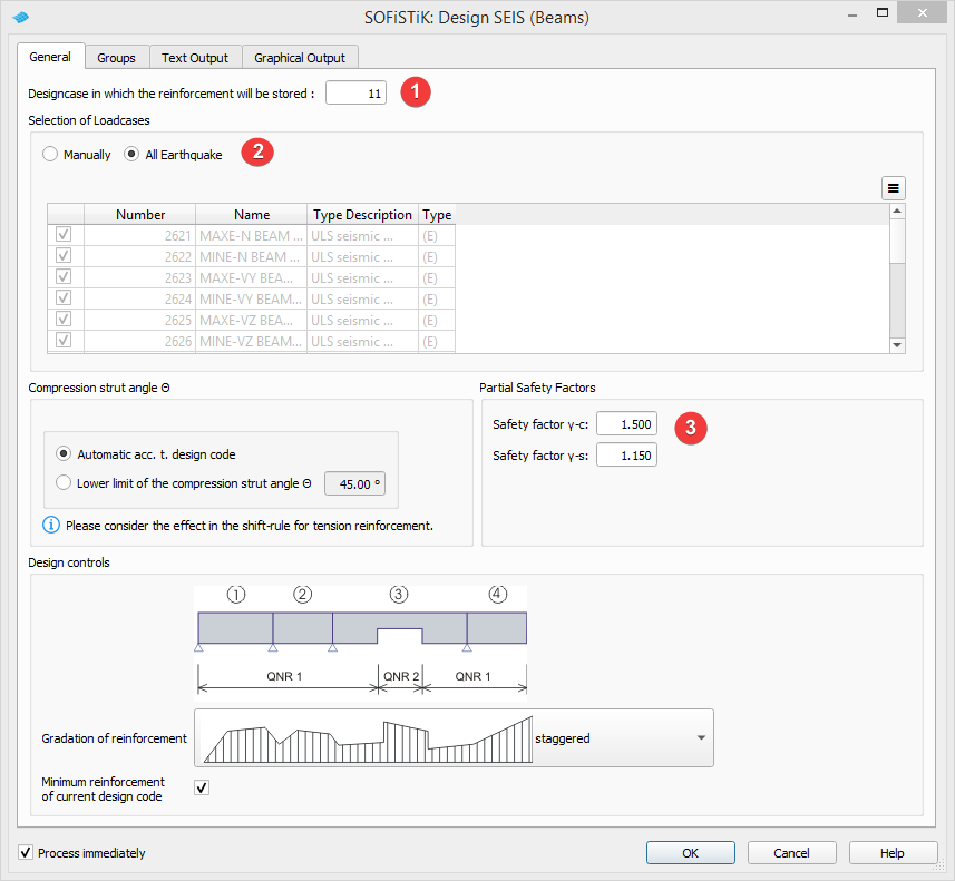
Similarly, in the task “Design SEIS (Beams)” the Designcase number will be set to 11, see point (1) in the picture below. Design loadcases for beam elements are automatically selected, see point (2), and the default values of the Partial Safety Factors, see point(3), are adopted acc. Eurocode 1998-1, chapter 5.2.4 (2).
Reinforcement envelope
Required reinforcement from different design cases needs to be combined to establish the reinforcement envelope. This will be done by an additional Text Editor Task, “Combine Design Results BEAM QUAD”
The input for the Text Editor Task is printed below.
+prog bemess urs:37.1
head Combine Design Results QUAD
CTRL LCRI 1,11          $ take results from distribution 1 and 11
CTRL LCR 20             $ accumulate both results and save maximum in distribution 20
end

+prog aqb urs:37.2
head Combine Design Results BEAM
rein rmod accu lcr 1    $ take results from distribution 1
rein rmod accu lcr 11   $ take results from distribution 11
rein rmod sing lcr 20   $ accumulate both results and save maximum in distribution 20
end
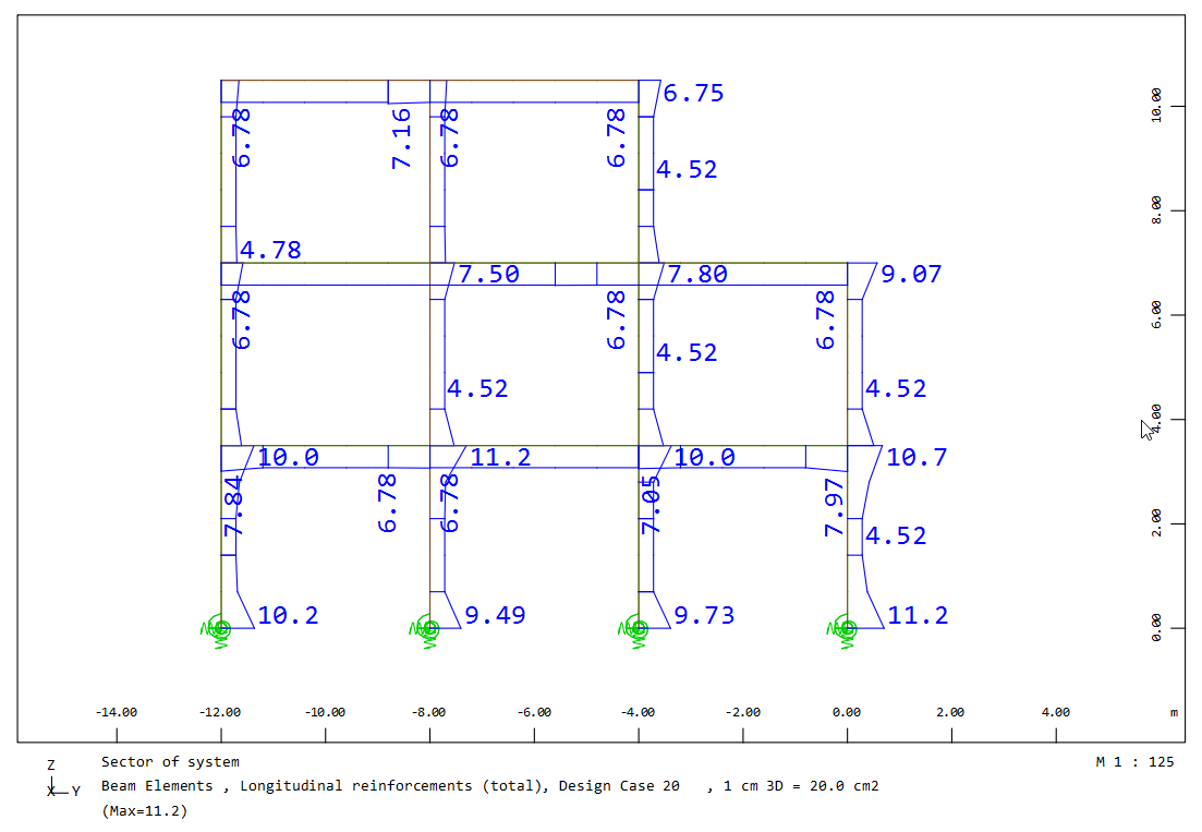
The final plot of the necessary beam reinforcement is shown in the picture below.